
Solar Cells
Update 01/01/2021
Inexpensive solar power banks are available at many locations now, ranging from supermarkets to computer stores. These power banks include a solar panel, control board, and a battery. I have disassembled one or two of these items to see what they have internally, and show an image below of a sample item.
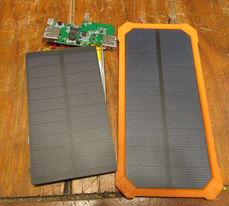
The original solar panel is on the left, and a larger panel from a slightly more expensive unit is on the right. At the top is the controller board. This unit has the ability to charge the battery from an external power supply (via a mini usb connector) as well as from the solar panel. The board can supply 5 volts via the two standard USB connectors on the sides. The battery is under the panel and is rated 4000 millamp hours. With an estimated consumption of 250 ma/hour for the board and instruments (not the camera or radio) such a battery should be able to run the system for 16 hours. The camera board (which will probably double power consumption) has a major impact and would only be usable during the day when solar power and battery power were both available. Similarly the radio may only be usable during the daylight hours (though low power telemetry type data could be sent at night).
And yes, if the panels are rated for 250 milliamps output, it will take 16 hours of continuous sun to charge the battery from a single panel like this, with no other drain. Charging time has to be brought up to less than 12 hours by using multiple panels, and consumption brought down by using sleep modes and cycling sensors on and off as needed.
5/13/2017
Update on the power supply for the payload.
Below is a picture of the solar panels laid out more or less how they would be on the payload. Note that the panels on top are the higher capacity 1.5 watt units, producing 250ma at 6 volts. The side panels are smaller, producing only 1 watt and 167ma at 6 volts. The 1.5 watt cells mass 43 grams each, and the 1 watt units mass 35 grams each. To get the four sides covered and the top would take 8 of the smaller cells and 2 of the larger cells, giving a total mass of (8 x 35) + (2 x 43) or 366 grams. That is a lot of mass. In the lower right corner you can see a solar panel to battery charger board, salvaged from a defunct cell phone charger unit. That little circuit has a mass of about 8 grams. A few diodes and other parts are needed to make this into a full blown power system, but the main parts are shown here.
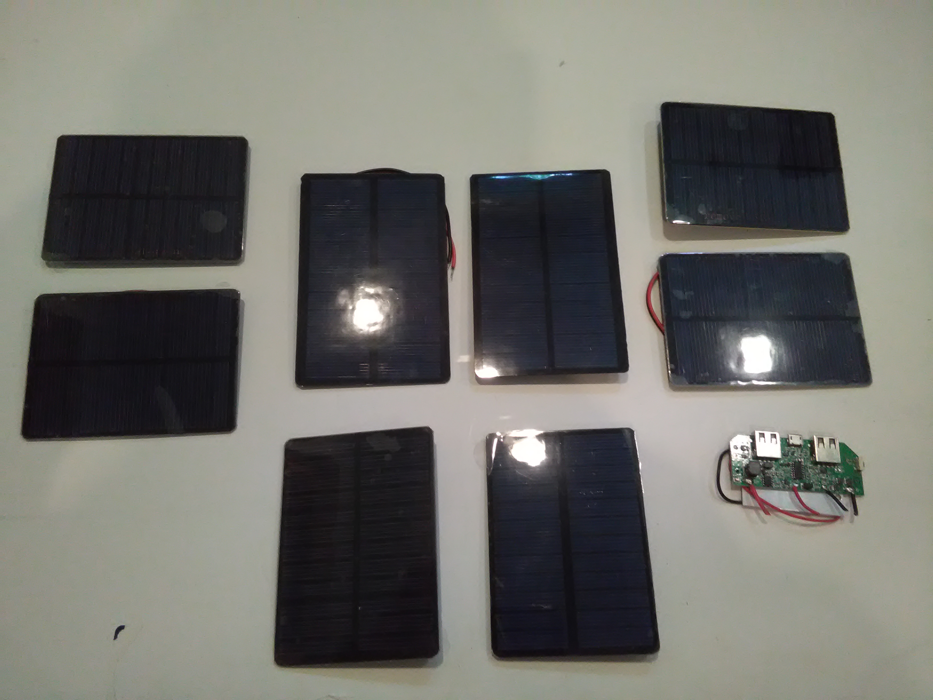
On Earth, in full sun, with all panels illuminated, the panels above should be able to produce over an amp at 6 volts. On Mars this will be reduced to 60%, and further as typically only one side of the probe will be illuminated at a time. By proper angling and use of the top panels, I hope to have a power input of 500ma during most of the day. It may be necessary to reduce the side panels to a single 250ma panel each to save mass.
3/14/2017
Solar energy is “free energy.” On Mars, the Sun shines just as it does on Earth and we can use that radiant energy to generate electricity. Because Mars is farther from the Sun than Earth is, the intensity of light is much reduced on Mars.
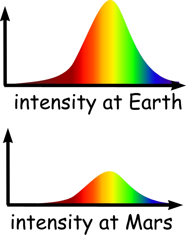
In fact, on the surface of Earth, at noon, solar energy is about 1000 W/m2. On Mars, the energy is only about 590 Wm2. So we have to figure at best, at noon, we only get 60% of what we would get at Earth. Even with this reduction, there is still a lot of power that the probe can tap into.
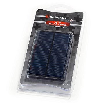
For testing, I purchased a variety of solar cells from Radio Shack. I have several of the 6 volt, 1watt units as well as a couple of the 6 volt, 1.5 watt units. The package says the 1.5 watt units produce 250ma maximum, presumably with sunlight shining right on them. On Earth this could charge a cell phone battery in about 10 hours. On Mars, we would need two of these cells to get the same power level. My little test current meter was pegged when I connected it directly to the 1.5watt unit in full sun a month or so ago!
For the balloon probe, we need to have at least two of these cells exposed at any time. With a square box for the payload, we would have two cells on each side. At worst we have two sides partly illuminated, which still should generate several hundred milliamps. At best we get two full on. Also, the top of the box would have one or two cells on it, and they would be illuminated at all times. We do need a circuit to block the cells off when the battery is charged or the cells are dark.
It is possible that we will have “too much” power during the daytime on Mars and could damage the batteries with too much current. The “extra” power would be good for running the camera, Raspberry Pi, flash storage, and radio which are all power hungry devices. Power design will be a balance between generation (solar cells), storage (lithium batteries), and consumption (instruments, radio, etc).