Fubarino SD PIC32Mx
2/24/2017
I recently rebuilt the laptop that I was using to develop the balloon software. This required me to reinstall the arduino IDE as well as the chipkit toolchain for the processor.
Do my dismay, I was unable to get anything other than trivial programs to compile properly. I had previously had issues with some libraries, where I had to comment out arduino specific code that caused the PIC compiler to fail. Now I found I was unable to get any libraries to work at all. I received a “jenkins” error. After several hours of experimentation and research online, I gave up on this iteration of the arduino and chipkit software. I also tried 2 back level versions but they were non-operational as well.
I have temporarily moved on to the Teensyduino 3.6 which has worked out well so far.
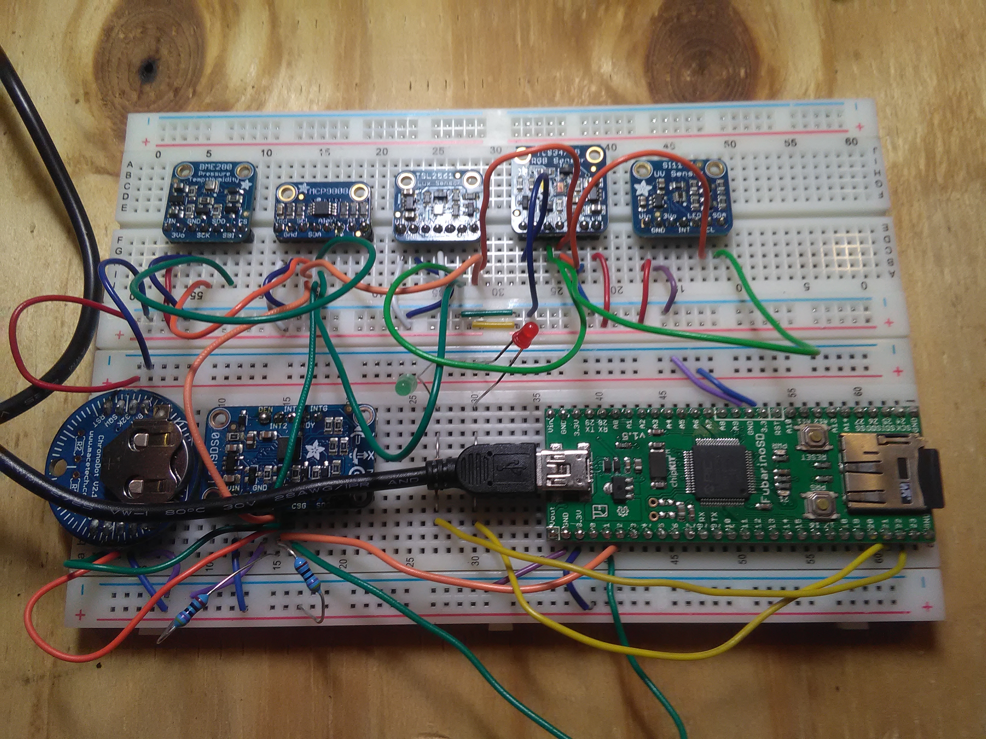
Below is a photo of my fubarino board before I moved to the teensy. Note that I have the core tied into a number of sensors. The meteorology sensors (upper protoboard, left side) were working properly. I added the lux and uv sensors, but was having more library problems before I took a break last year.
Earlier in 2016———-
After several months of intermittent experimentation, I have gotten what I consider to be the core of the balloon processor working. This consists of the 9DSOF sensor, which is programmed to give raw readings and also AHRS data, and the real time clock module. The Fubarino SD already has the built in SD card reader connected to the SPI interface.
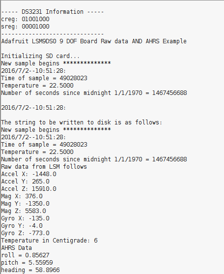
The program reads the sensors and logs the data to the SD card, and also displays the results on the screen.
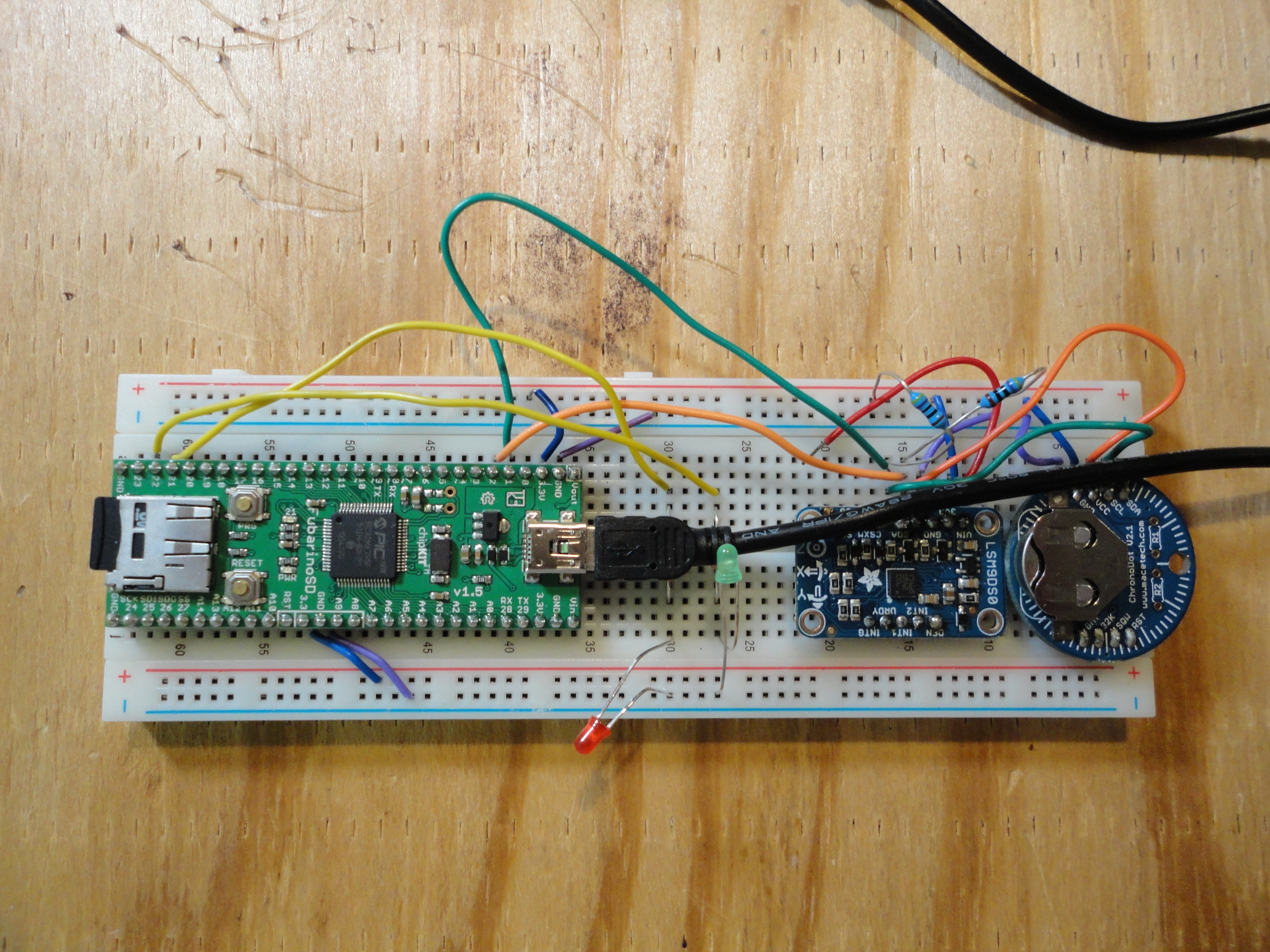
Next to add is the secondary board with the meteorology instruments. Program output is shown below and a shot of the board. I will have the code up on github soon once I get my account created.
Core hardware shown above: The Fubarino itself on the left, with the micro sd card reader pointing left, the usb for programming comes out towards the right of the Fubarino board. To the right of the Fubarino is the 9DOF board, which has the gyros, accelerometers, and magnetic sensors. This is the AHRS system. On the far right is the temperature compensated clock module, which has a self contained battery. This is the heart of the system. Other sensors will be added on via SPI, I2C, or via GPIO/analog lines.
Board summary below:
This board offers the powerful Microchip PIC32MX single chip controller. The 795, used in the 1.5 version, has 512kb of flash and 128kb of RAM. The chip also has a full 32 bit MIPS 4000 class processor running at 80Mhz. This makes it far more powerful than the Mega2560. There may still be issues with the 3.3 volt and 5 volt compatibility with the test instruments. Hopefully the voltage level converter boards will help with this. More advanced chips, such as the MZ, have even more flash and RAM, making it possible to run a real OS and good RTOS on the hardware.
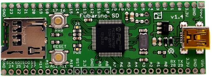
Here is the SD board that I recently purchased from Microchip (for about the cost of a Pi!) and which will likely take the place of the 2560:
Note the SD card reader on the device. This, plus the FAT libraries, should allow for the logging of sensor readings, and possibly images, as the data is gathered. Actual size of course is much smaller.


