UV and RGB Sensor
Because Mars has such a thin atmosphere, a lot of UV and other radiation hits the surface. This could be bad for astronauts who are out and about, and the balloon should track the UV levels. For tracking UV, I selected the Adafruit SI1145 board.
Here are the specs:
- calibrated UV sensing element that can calculate UV Index.
- I2C so just about any microcontroller can use it
- the sensor also has visible and IR sensing elements
- can run from 3.3v or 5 volts on the breakout board
Here is the manufacturer page: SI1145
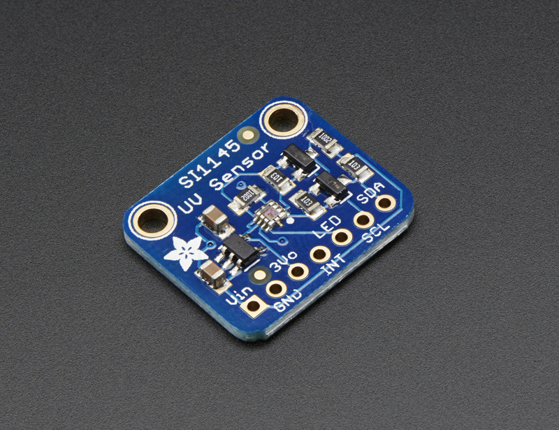
Here is the image:
I also selected an RGB sensor to get a better color resolution on the ambient light. For this, I selected the Adafruit TCS34725 breakout board.
Here are the specs:
- has RGB and Clear light sensing elements
- an IR blocking filter, integrated on-chip and localized to the color sensing photodiodes, minimizes the IR spectral component of the incoming light and allows color measurements to be made accurately
- The filter means you’ll get much truer color than most sensors, since humans don’t see IR
- The sensor also has an incredible 3,800,000:1 dynamic range with adjustable integration time and gain so it is suited for use behind darkened glass
- can power the breakout with 3-5VDC safely and level shifting for the I2C pins so they can be used with 3.3V or 5V logic
- a 4150°K temperature LED with a MOSFET driver onboard to illuminate what you’re trying to sense. The LED can be easily turned on or off by any logic level output.
Here is the Adafruit page: TCS34725
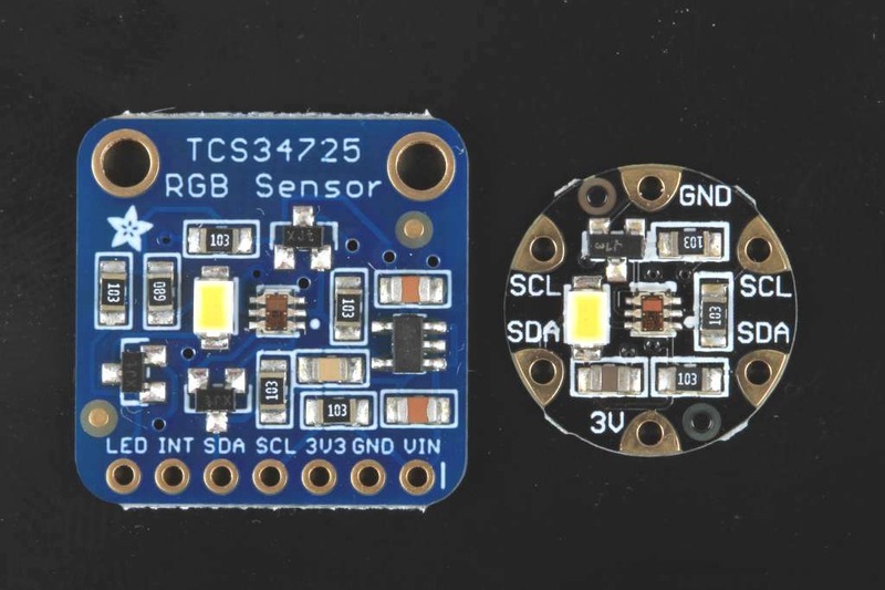
Here is the sensor (I bought the square one on the left):
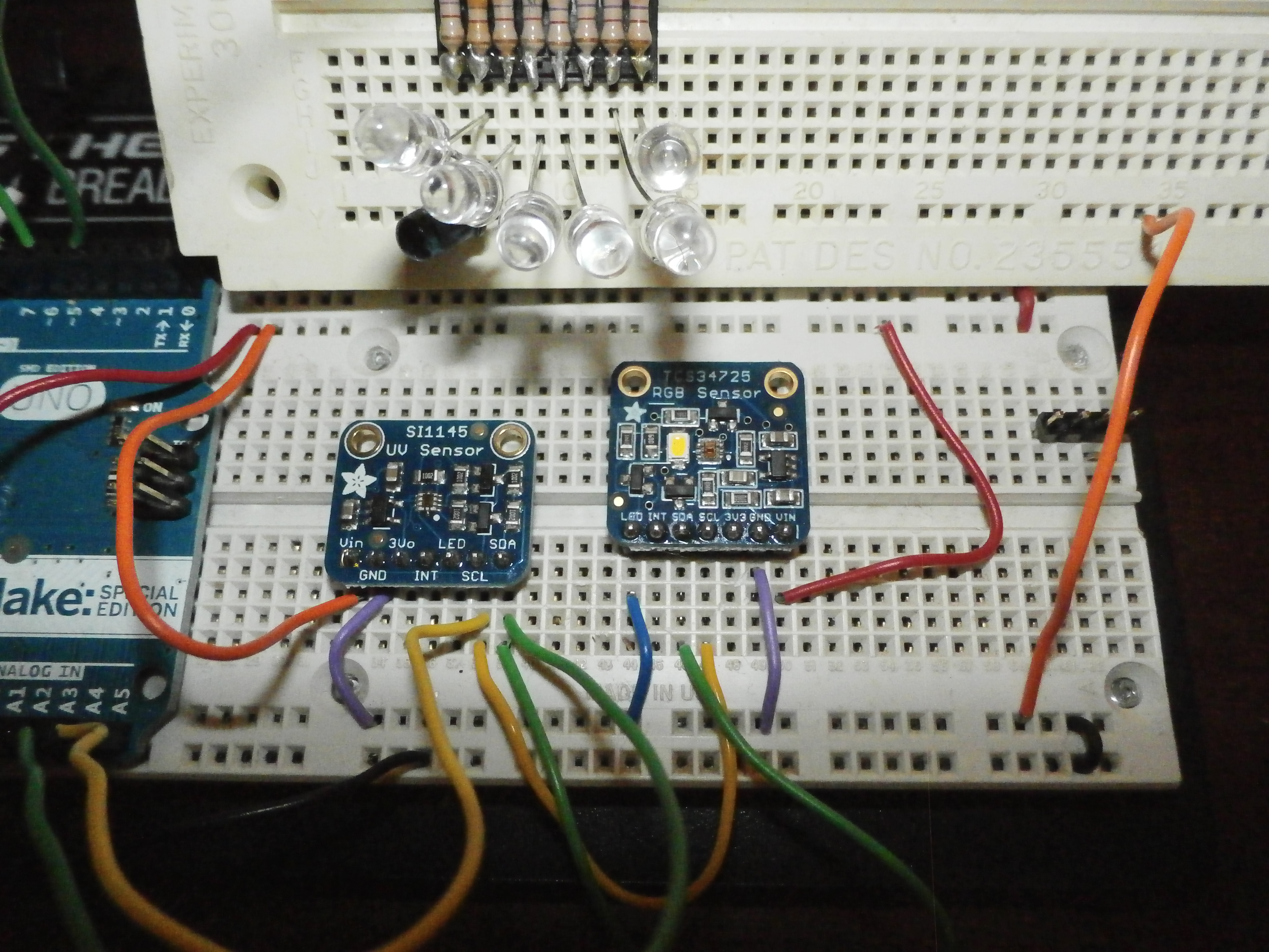
To test these guys, I made up a test rig with multiple colored LEDs driven by my Uno, with the Uno reading the sensor results after it changed the LED colors. After fiddling with the I2C bus a bit (these do not seem to need pull up resistors) the results were acceptable. I combined the two sketches from the Adafruit site and adapted the code for my purposes.
Here is the test rig. You can see how I had the LEDs above the sensors, and the Uno was able to run IR, visible (Red, Orange, Yellow, Green, Blue) and UV colors using pwm.
The program and hardware produced output like that below. Note that I moved the LEDs around over the sensors, to get different colors above the sensors, and you can see the difference in the snapshots below. Here is the code: uno_pwm_1145_34725_test_12_26
Adafruit SI1145 test
Found Si1145
Adafruit TCS34725 test
Found TCS34725sensor
inside of main loop
===================
Brightness value= 0
Adafruit SI1145 read and print code
Visible: 261.00
IR: 258.00
UV: 2.00
Adafruit TCS34725 read and print code
C: 275 R: 133 G: 115 B: 111
===================
Brightness value= 255
Adafruit SI1145 read and print code
Visible: 295.00
IR: 335.00
UV: 20.00
Adafruit TCS34725 read and print code
C: 466 R: 148 G: 162 B: 276
===================
Brightness value= 255
Adafruit SI1145 read and print code
Visible: 264.00
IR: 504.00
UV: 4.00
Adafruit TCS34725 read and print code
C: 909 R: 190 G: 280 B: 611
===================
Brightness value= 255
Adafruit SI1145 read and print code
Visible: 263.00
IR: 316.00
UV: 3.00
Adafruit TCS34725 read and print code
C: 1261 R: 368 G: 459 B: 836


