ESP32 Processor Board
12/29/2017
The DevkitC board had some limitations. It was a hassle to do prototyping due to the greater width. It also lacked built in sdcard reader, which meant I would have to wire one up for extra expense and complexity.
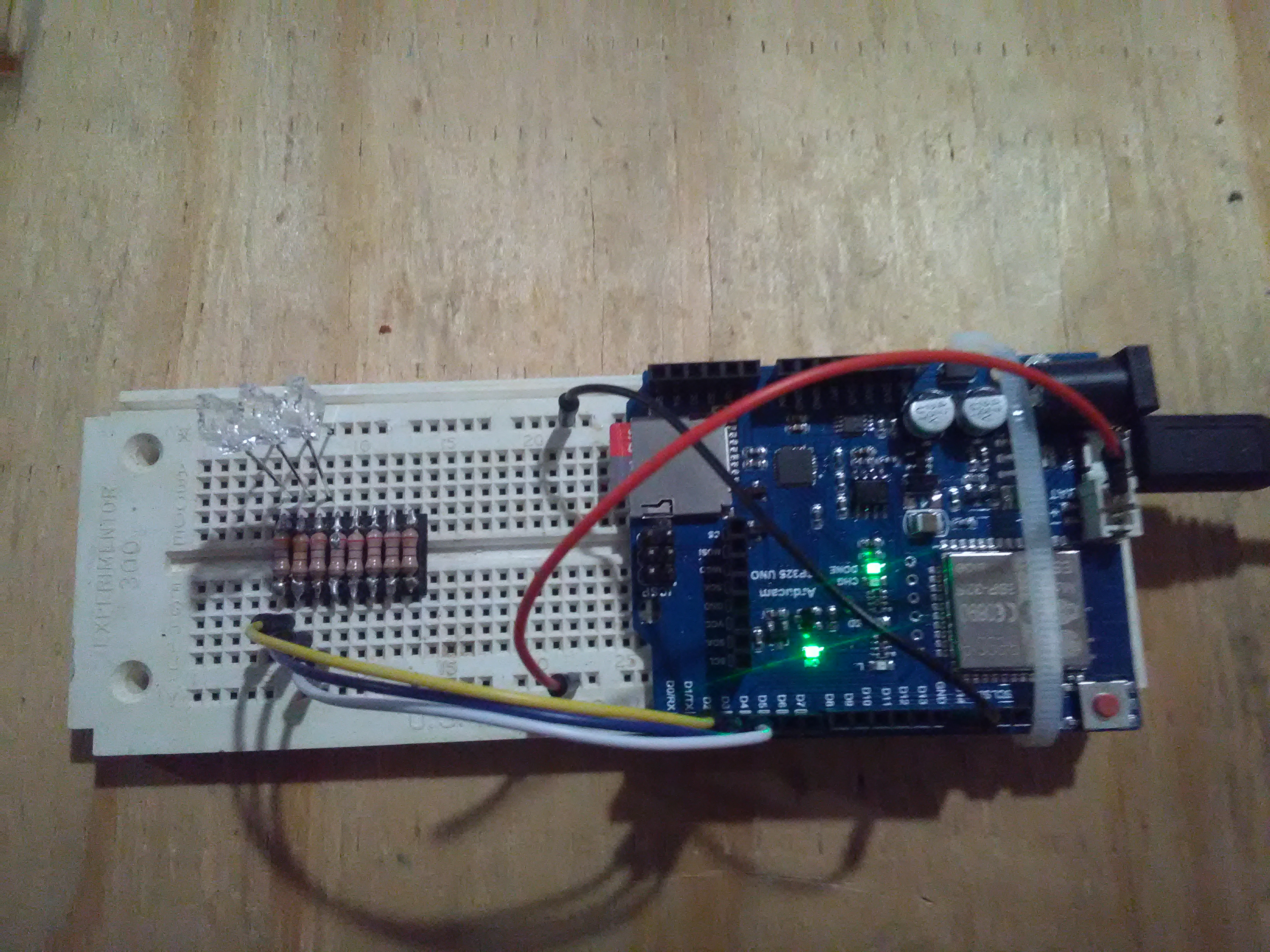
However, I found that the Arducam folks had produced their own custom ESP32 board. This board is very handy, having built in micro_sdcard reader, arduino type pin connectors, connector for their arducam cameras. The built in sdcard reader will be very handy to write buffered sensor data. I have tested the sdcard reader using the sample code and it works ok.
Here is a picture of the new board with some LEDs connected for testing.
9/17/2017
Because the esp32 devc board is so wide, I had to cut a prototype board in half and then double sticky tape it back together to be able to get started prototyping and testing. Below is the final product.
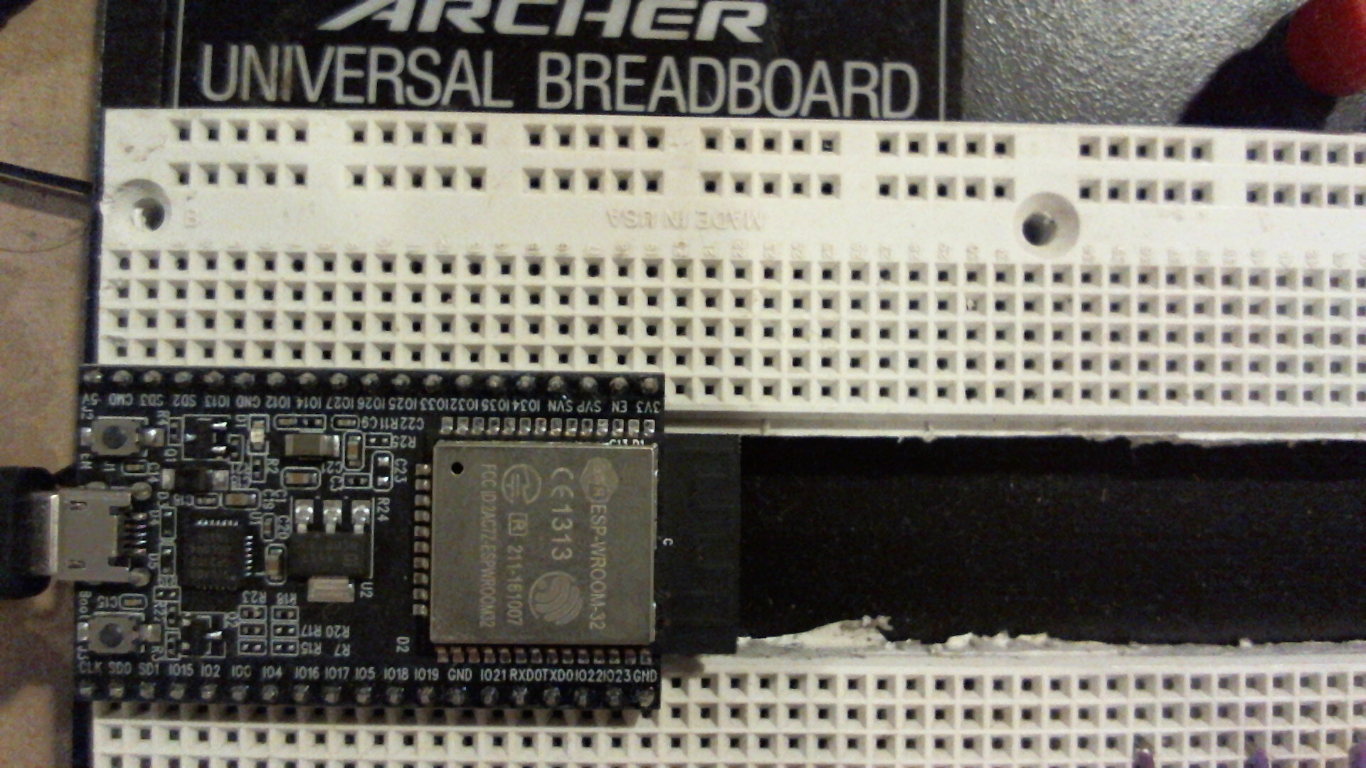
I have done some initial testing of the esp32 board. One test involved the use of the Hall effect sensor in the chip. I ran the example program and moved a refrigerator magnet close, and sure enough, the sensor values did change. Another test involved the extraction of the processor ID.
Most interesting though was the testing of the wifi client software and function. This demo, from the good folks at Sparkfun, allows for the posting of data to their website via the esp32. I had to create a special no-security wifi router for this. The program needed some values for the remote site, including the stream id and private key. It was amazing to see the output of the esp32 go across the internet and arrive at the server and be viewable. This is the type of function we need for data transfer from Mars.
One fellow has been able to transmit data 10km from a stock esp32. This is impressive as he made no change to the transmitter. By adding a beefier transmitter, and using a better receiver, we should be able to get the data from the balloon to a satellite in orbit.
7/12/2017
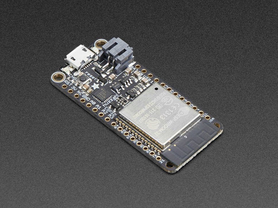
An ESP32 board has arrived in my mailbox. This is the ESP32 DevC board, which is slightly different from the Adafruit board shown below. The DevC board was available in 2 days and had the same processor etc, lacking only the battery charger circuit. Since this battery function will be handled by a single point in the Mars balloon, this function was not necessary. This DevC board is the Espressif official development board, and appears to be well supported and standard.
The DevC board has one unfortunate feature, which most of the similar boards seem to suffer, and is the unusual width of the board. As near as I can tell so far, the board is too wide for use with a standard protoboard if at least one row of holes is desired on the sides of the board. In this case, other options could include the use of a copper plated board with through holes, replacing the pins with female connectors similar to the Arduino board, or running some wiring under the board on the protoboard.
Multiple development software tools are available, including those from the vendor, as well as the Arduino plug ins. As long as the basic functions are operational, Arduino should work well enough. One interesting function of the ESP32, which is the ULP, may not be as well supported by Arduino. The ultra low power processor is a very cool technology, which in theory could be used. However, according to the docs from Espressif, low power modes are available for the ESP32 which would allow the cpu to be running without the issue of the programming of the ULP. These low power modes may be sufficient and operational at this time.
7/7/2017
This is a new board from the folks at Adafruit using the new ESP32 processor module.
Here are specifications from Espressif about the ESP32:
- 240 MHz dual core Tensilica LX6 microcontroller with 600 DMIPS
- Integrated 520 KB SRAM
- Integrated 802.11b/g/n HT40 Wi-Fi transceiver, baseband, stack and LWIP
- Integrated dual mode Bluetooth (classic and BLE)
- 4 MByte flash include in the WROOM32 module
- On-board PCB antenna
- Ultra-low noise analog amplifier
- Hall sensor
- 10x capacitive touch interface
- 32 kHz crystal oscillator
- 3 x UARTs (only two are configured by default in the Feather Arduino IDE support, one UART is used for bootloading/debug)
- 3 x SPI (only one is configured by default in the Feather Arduino IDE support)
- 2 x I2C (only one is configured by default in the Feather Arduino IDE support)
- 12 x ADC input channels
- 2 x I2S Audio
- 2 x DAC
- PWM/timer input/output available on every GPIO pin
- OpenOCD debug interface with 32 kB TRAX buffer
- SDIO master/slave 50 MHz
- SD-card interface support
All this for (a little) under $20 bucks. For the balloon project, the big selling point is the built in WiFi. Research has shown that there are many possible communication options that could be used to test or simulate the system as it would work on Mars. However, they all suffer from range limitations, driver issues, low bandwidth or other problems.
For testing purposes, the use of WiFi seems like a good idea. It offers high bandwidth (on the order of the NASA protocol), inexpensive hardware, and good software support. The goal is to integrate this board with the payload, and have the esp32 handle upload of images and sensor logs. For testing, this could be done with sftp, tftp, http, or another protocol as long as the data is transferred within the time window and without errors.
Soon I will be buying one of these chips and getting to work on testing with the Teensy 3.6 and Pi Zero.