Optical Flow Sensor
4/3/2017
The ADN3080 optical flow sensor was interfaced to the Teensy 3.2 for initial testing with the new platform. The device was previously tested with an 8 bit Arduino.
After just a few tweaks, I was able to get my Teensyduino 3.2 to work with the flow sensor. I was able to get back the motion information as well as the low resolution image data.
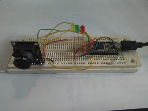 The optical flow sensor uses SPI, shown here with the T3.2
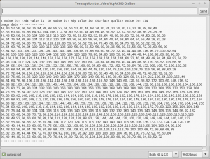 Here is the program output, showing the movement data at the top and the image data at the bottom. The image data is optional, and could be captured to a csv file to convert to an image later.
teensy3p2_ADNS3080_4_1_2017 (1).tar
Soon this sensor will be incorporated into the rest of the T3.6 system.
2/24/2017
After the meteorology instruments are up and running, the optical flow sensor will be next. This may take some doing as the code was written for the 8 bit arduinos. However, the teensyduino has much more memory and resources, so it should be able to process the data and even save it to the sd card for later analysis.
Update: 12/3/2015
I have received the unit that I ordered. I have interfaced the ADNS3080 to my aduino UNO and gotten readings out of the sensor. The lens allows for something like 20 turns, which should allow for adjusting the focus to range from closeup to infinity. I will post my code that does basic readings soon. There is information out there but some is rather obscure and it seems difficult to find the libraries.
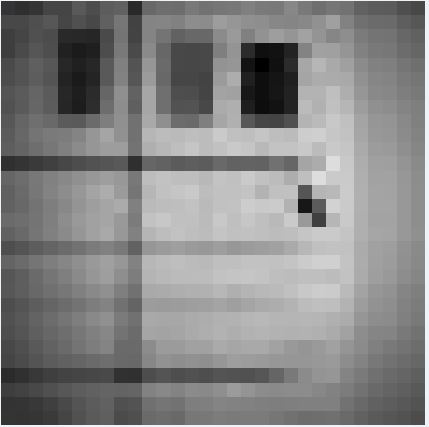
Here is an image captured using the sensor:
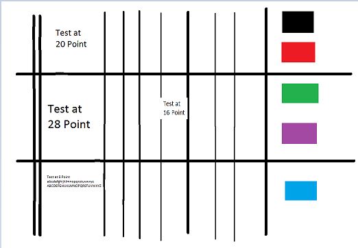
This is an enlarged image to show the actual pixels. Note the image is 30×30, which is the max that this type of sensor comes with. Below you can see the image that I used for testing the camera (scaled to fit the page here). The fine lines did not come out at all and the text just shows up as colored blobs from a distance of a few feet away. The colored blocks also showed up but not with the same density-this is probably a function of the sensitivity of the chip itself.
The sensor outputs numeric values for the image. You have to take those numbers and import them into another tool to generate and image like I did above. I saved the numbers as a csv file and then imported them into A-VEKT program. This program converts a csv into an image. Be sure to tell it to use a single 8 bit value for the A as we have one byte/pixel monchrome data.
Background:
The IMU can be used to determine the motion of the payload as it floats over the surface of Mars. Another tool that can be used for this purpose is an optical flow sensor, such as those used on optical mice. The one in most common use appears to be the adns3080. This is a single chip unit, with a 30×30 sensor and an onboard DSP to process the imaging system. The sensor can provide values for the movement in both the x and y directions, as well as actual image capture data. The values must be used in conjunction with altitude data to determine actual movement distances.
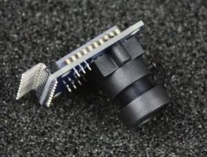
I purchased a unit, which is similar to the one shown below:
At the time of this writing, the unit above is less than $20 from this vendor: http://www.aliexpress.com/item/ADNS3080-Optical-Flow-Sensor-Horizontal-Position-for-APM2-5-Flight-Control-Board/1404445315.html
Note that these optical sensors can be extracted from defunct optical mice, but many mice seem to have the cheaper units such as the 2051 which have much less resolution and other limitations. Some laser based optical mice may have usable sensors, in addition to neat IR lasers, but be careful! The IR lasers can damage your eyes if you look at them without proper protection. The optical flow sensors do not require the IR lasers and will work well outside with natural light.

